Arnaud Vanderveken
Graphics programmer @ I-Illusions
Ex Ubisoft Annecy | Graduate in Game Development from Digital Arts & Entertainment (BE)

Featured work

My work at Ubisoft Annecy
C++ HLSL Anvil DLSS FSR RenderDoc NSight

My work at I-Illusions
C# HLSL Unity 6 URP HDRP RenderDoc
PicoGine 3
C++ HLSL Custom Engine Vulkan 1.3

PicoGine SC
C++ HLSL Shader Compiler
Vulkan Renderer
C++ GLSL Vulkan 1.0
Portal Framework
C++ HLSL DX11 PhysX NSight
Portal Prototype
C# HLSL Unity 5 BiRP
Software/Hardware Rasterizer
C++ HLSL DX11 NSight
My work at I-Illusions
Jun. 2024 - Now
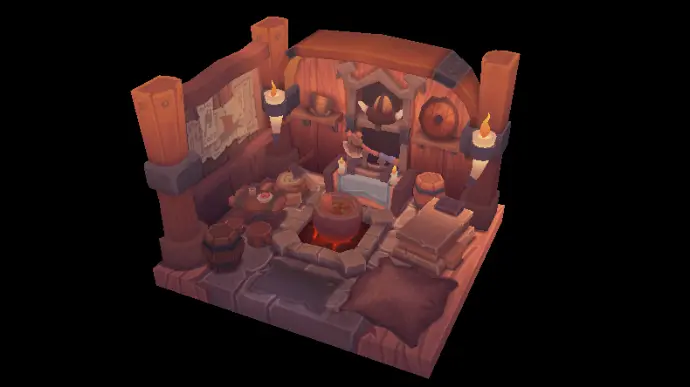
I joined I-Illusions in June 2024 to work on their next project, made with Unity. Graphics programming in Unity was something new for me, so to get started, my first task was to port custom shaders and render passes from a previous project made with the built-in rendering pipeline (BiRP) to both the universal (URP) and high-definition rendering pipelines (HDRP), and compare them to other solutions that were included in these two render pipelines. The goal was also to compare URP and HDRP in terms of usability, performance and visual quality to determine which one will be used in the new project.
A key element in both the previous and new project is the terrain rendering system. The original system was using four layers, one of them (a rock/cliff layer) being mapped tri-planar for near vertical surfaces, blended using a splat texture and bicubic sampling for smoother transitions. For the new project, we wanted to extend the amount of layers and separate the snow layers from the others to have better control on how they blend together. To achieve this, I designed a new system in conjunction with my colleague responsible for the terrain generation where all the layer's textures are grouped in a texture array, and the splat map texture is replaced by a structured buffer of 16-bit packed values (4 bits for the snow texture index, 4 bits for other non-snow texture index, and 8 bits for the snow layer thickness), grouped together in pairs to respect a 32-bit alignment. This allows me to compute bicubic weights on a 4x4 kernel, accumulate those weights based on the indices stored in the buffer while computing the final snow height, and finally sample each texture only once. I can then blend the snow and non-snow layers separately before merging them using either noise (for a sparse snow effect on flat ground) or the crevices from tri-planar rocks. It is also easy to add procedural snow on the top-facing parts of the rocks by simply adjusting the blend weights based on the normal vector angle.
Some other aspects of this terrain rendering system include generating a custom shadow map for the terrain, where instead of being rendered in the four shadow cascades, the shadow map is generated by raymarching the height map towards the sun. Since there is no real-time dynamic sun, this shadow map only needs to be regenerated when the sun gets moved in the editor, or the in-game edit mode. The terrain normal map is also generated based on the height map and takes the snow layer thickness from the structured buffer too. The terrain uses Unity's instancing system, as well as dynamic tessellation based on distance. I also made another shader that allows objects to blend with the terrain, by lerping the terrain textures and the terrain normals onto the object.
At some point, I also helped setup the FSR 3.1 Unity plugin for an update of Shredders, a previous project from I-Illusions, and experimented with various settings to get the best visual quality considering the pace of the game and other effects like snow particles which generates a lot of fast-moving pixels.
For debugging and analysis, I was mainly using RenderDoc. Thanks to its integration to Unity, I was able to take frequent captures to ensure proper rendering, GPU data integrity, and debug shader execution.
Topics Covered
- Unity
- Built-in Render Pipeline (BiRP)
- Universal Render Pipeline (URP)
- High-Definition Render Pipeline (HDRP)
- Custom terrain shaders (tessellation, displacement, instancing, shadows, tri-planar mapping, ...)
- Object-terrain blending shaders
- Compute shaders
- AMD FSR 3.1 (for Shredders)
Programs and tools
- Unity 5/6
- RenderDoc
- Visual studio
- Plastic SCM (Unity version control)
- AMD FSR 3.1
My work at Ubisoft Annecy
Oct. 2023 - Feb 2024
During my 4 months internship at Ubisoft Annecy, I worked on an unannounced project using a branch of the Anvil pipeline. Therefore, there are no visuals I can show and I'll go over my tasks without mentioning specific details about the project.
When I arrived, my first task was to add Nvidia's DLSS 3 to the existing upscaling methods already implemented. This was a good entry point to discover the project's structure, rendering pipeline, and in-game debug options. Within 3 weeks, DLSS 3 was up and running on any resolutions with all the quality settings, and the debug options to enable it while waiting for the UI team to add it to the game options. To help me through this task, I mainly used Nvidia NSight for debugging and making sure everything was setup correctly. I couldn't use the integrated RenderDoc implementation because it wasn't compatible with DLSS.
I then spent the next three weeks on various debugging tasks on PC and consoles, as well as reworking some existing rendering systems. Some examples are reworking the existing FSR 2 implementation to fix some artefacts and improve visual quality, and tweaking the cascaded shadow system for better splits in the distance. Here I switched mainly to RenderDoc for debugging, because the capture hook was already implemented in the engine, and I already had some experience with Nvidia NSight with my previous task.
Finally, I spent the remaining weeks on porting the Anvil editor from our branch to use the new Vulkan rendering pipeline instead of the legacy DirectX 11 pipeline. When I joined the project, the game engine was already upgraded from DirectX 11 to Vulkan but the editor was still running on DirectX 11, and thus wasn't benefitting from the optimizations made in the new Vulkan pipeline. To make that transition, I had to dive into the build system to allow for a Vulkan editor target to build, with all required defines and files being included. Then, I went through all editor related source files to ensure they'd compile correctly on that new build target, and I also had to browse all Vulkan related files to make them compile for the editor, as they were all "game only". The trickiest part was to break all the tightly coupled connections between an editor build and DirectX 11. In the end, I was able to build and run the Anvil editor from our branch with Vulkan, quite stably, although some actions and some debug views weren't working properly. With my internship coming to an end, I didn't have time to fully test and fix everything.
Topics Covered
- Vulkan
- Image upscalers
- Nvidia DLSS 3
- AMD FSR 2
- Cascaded shadow maps
- Editor
- Build system
Programs and tools
- Ubisoft Anvil engine and editor
- RenderDoc
- Nvidia NSight
- Visual studio
- Perforce
- Nvidia DLSS 3
- AMD FSR 2
PicoGine 3
This project is an evolution of my previous work on a game engine. In this new version, I will focus more on graphics and rendering, rather than a broader engine, since this is the domain I want to specialize into. Therefore, I will rely on more libraries to build the core of the engine, such as a entity-component system like EnTT for example.
The main goal is to incrementally add new rendering features using both Vulkan and DirectX 12 under a common abstraction. For now, I focus more on the Vulkan side, because I have more reference for it.
To make the shader compilation easier, I made another project called PicoGineSC. More info on its project page.
The project is available on GitHub!
This project is still work in progress at an early stage.
Topics covered (so far)
- Win3
- Raw input devices
- Vulkan
- HLSL
- DirectX Math
- Xinput
- Assimp (Open Asset Import Library)
- stb-image
- EnTT Entity-Component System
- Various programming patterns (i.e. game loop, singletons, ...)
Planned features
- [✓] Visual Leak Detector
- [✓] Win32 for window and system events
- [✓] Vulkan renderer
- [✓] Keyboard and mouse control with raw input
- [✓] Controller support (XInput)
- [✓] Entity-Component System (EnTT)
- Graphics abstraction layer
- DirectX12 renderer
- PBR Materials
- Advanced graphics techniques (i.e. batching, instancing, multi-threaded command recording, async compute, ...)
- GPU particles
- Specific rendering systems for terrain, grass, foliage, ...
- Volumetric effects
- Various Post-Processing effects (tone mapping, bloom, depth of field, ...)
- Anti-aliasing solutions (MSAA, TAA, FXAA)
- Upscalers (DLSS, FSR, XeSS)
- Raytracing/Pathtracing (for things like G.I., shadows, ...)
- Entity-Component system
- ImGUI for simple editor and debugging
- FMod for audio
- And many more to come in the future...
Reference Materials
- vulkan-tutorial.com
- 3dgep: Learning DirectX 12
- Vulkan 3D Graphics Rendering Cookbook (2nd. ed.), S. Kosarevsky, A. Medvedev, V. Latypov
- Mastering Graphics Programming with Vulkan, M. Castorina, G. Sassone
- GPU Zen 1: Advanced Rendering Techniques, W. Engel
- GPU Zen 2: Advanced Rendering Techniques, W. Engel
- GPU Zen 3: Advanced Rendering Techniques, W. Engel
- Graphics Programming Conference 2024, Breda, The Netherlands (attended in person)
Win32, window, and inputs
Initially, I was planning to use the SDL library to create the window as well as handle inputs. Because I will not use other features from SDL, I decided to still implement it myself using Win32 since I've done it multiple times already and might be even faster than implementing SDL.
The window supports resizing, minimizing, maximizing, and toggling full screen borderless mode. It also supports multiple monitors, and can move the window across screens with the Windows shortcuts (Win + Shift + Arrows) even in full screen borderless mode.
For the inputs, I used raw input devices for the mouse and keyboard to try something new. I also added controller support using the Xinput library.
Vulkan and DirectX 12
The project will support both Vulkan and DirectX 12. I made separate build targets which both have a preprocessor define for their specific API. This allows me to batch build all targets to ensure the changes made with one API don't beak the other.
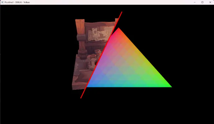
At the moment, only a basic Vulkan implementation is available, which was made following the vulkan-tutorial.com, similarly to my previous Vulkan Renderer project except this time I used HLSL for the shaders instead of GLSL. The next step is to cleanup and restructure the code properly, then start working on abstracting all the key elements. Then, I'll make a similar DirectX 12 implementation following this 3dgep: Learning DirectX 12 guide.
Once the barebone core of both API works under the same abstraction, I will start implementing more advanced topics, most likely in Vulkan first because I have more reference material for that API.
PicoGine SC
This project is a small shader compiler made in conjunction with PicoGine3. The main goal of this shader compiler is to interpret some Json-style metadata to generate all the required shader targets and compile them with the DirectXCompiler (DXC for short).
The project is available on GitHub!
This project will evolve with the progress of PicoGine3 as it will bring other more complex shaders to compile and might reveal some cases that aren't handled properly at the moment.
Invoking the PicoGineSC
When building the Release target of the project, the path to the output executable is set to an environment variable to make it accessible for any other projects. In my case, I added a custom build step in the project settings of PicoGine3 to always invoke PicoGineSC to check for new/modified shader files, even when no changes were made to the project's files.
The command to call PicoGineSC will look like this: "%PGSC_PATH%PicoGineSC.exe" -vk "$(SolutionDir)Shaders" "$(OutDir)Shaders" (example from PicoGine3). The first argument determines the output file format: -vk generates .spirv for Vulkan and -dx generates .cso for DirectX 12. The second argument is the input folder that will be parsed to compile all .hlsl files in it. Finally, the third argument is the output directory where all compiled targets will be stored, as well as a log file from the compilation process.
Shader metadata and compilation process
The first step is to parse the input directory to find all .hlsl files, other files and sub-folders being ignored. Therefore, include-only files should use the .hlsli extension in order not to cause unnecessary errors or warnings. The processing of all these files is then spread across multiple threads.
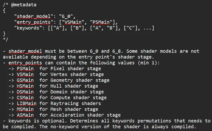
The metadata is a Json-style comment at the top of the shader file. It has two mandatory fields and an optional one, as described in the screenshot on the left. This allows to choose a per-file shader model, compile multiple entry points within the same .hlsl file (for different stages for example), and define keywords to make different variants of the same logic (added as preprocessor #define). If the metadata is missing or doesn't follow the the correct model, the file is ignored with a corresponding error being output to the invoking program's console output and the log file in the output directory. PicoGineSC also searches the file for the given entry point, ensuring it exists in the file, and outputs an error before starting the compilation if it is missing.
Once all targets have been identified, PicoGineSC checks for already up-to-date outputs (by comparing the last write time of the output shader and the source .hlsl file. ToDo: handle included files.) and skips unchanged files. All those target filenames are stored for a final cleanup pass. One all targets have been compiled, PicoGineSC parses the output directory to delete all shader outputs (both .cso and .spirv) to delete old output that are not required anymore (i.e. deleted source files or keywords or a change in the targeted API).
Vulkan Renderer
This project was my first time working with Vulkan. I implemented the tutorial available on vulkan-tutorial.com in a new project, separate from any existing project, in order to focus on understanding how Vulkan works and link elements to my current knowledge of graphics programming and other APIs like DirectX 11 and 12. I skipped the last chapter about compute shaders, as it was going out of scope for this project.
The project is available on GitHub!
Implemented features
- Vulkan graphics pipeline
- Vertex buffer
- Index buffer
- Uniform buffers
- Depth mapping
- Loading mesh from file
- Loading textures from files
- Generating and using mipmaps
- Multisample anti-aliasing (MSAA)
- PBR metallic roughness shading (for camera model only)
Credits
All credits to the website vulkan-tutorial.com for their code and the resources they used. The images showed below comes from their website too, to more easily show the effects of mipmaps and MSAA.
Credits to Yannick Deveux for the camera model and textures for the PBR example.
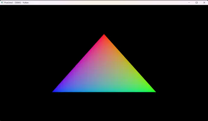
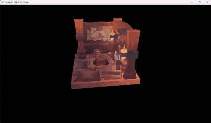
Rendering a model
After setting up the pipeline, a render pass, loading a model and it's texture, filing the vertex buffer and index buffer and binding everything together, this was the first 3D render of the project. It does not have mipmaps or MSAA yet, which will be added in the next sections.

Generating and using mipmaps
Mipmaps can be used in order to reduce some artefacts related to the texture, like a flickering on a far moving object. They are lower resolution versions of the original texture. The further the rendered triangle, the smaller resolution texture will be used. This basically blurs the pixels of the texture to reduce the flickering effect caused by a pixel's color changing too fast from frame to frame due to movement for example. The effect of mipmaps is not the most obvious here, as the scene isn't really deep.
Applying MSAA
MSAA, or Multisample Anti-Aliasing is used in order to smooth the edges of a model, by sampling each pixels at multiple locations, and not only it's center. The more of those sample points are inside the rendered triangle, the more opaque the color will be. This usually leaves a border of semi-transparent pixels around the triangle that softens the jagged "staircase" effect on the edges, and make them appear smoother. Of course, the more sample points, the heavier the computation becomes, so it is important to find the correct balance between quality and performance.

PBR render example
This example uses a camera model made by my artist friend Yannick Deveux for his Game Asset Pipeline class. This includes the 3D model and textures for base color, normal, ambient occlusion, metallic and roughness.
I used all these textures to shade the model following the Cook-Torrance BRDF workflow.
Portal Framework
This is the framework that will be used to recreate Portal for which I already made a prototype in Unity (available here).
At the start of the course, we receive a starter project with barebone implementation of the Overlord engine, consisting of the game loop, PhysX, ImGUI, and an implementation of DirectX11 with the Effects Framework. From this point, we have to implement the different materials and shaders required for the rendering of the game, as well as some PhysX related elements.
As this project will serve as the final assignment for a course, where everyone recreates an existing game, I will not make this code available publicly, to prevent any potential plagiarism issues from other students that also chose Portal.
Credits
Credits to Thomas Goussaert , DAE lecturer for Graphics Programming 1 and 2, for the base framework implementation.
Hardware animations & Shadow mapping
This small demo shows the results of the hardware animation, as well as the shadow mapping. For the animation, the current frame's bones transforms are interpolated using the current animation tick and the animation's key frames. The result is then passed to the shader to be used by the vertex shader. Each vertex can be skinned to a max of 4 bones, using the according blend weights.
For the shadow mapping, a render target is used to render the depth of every objects in the scene relative to the main directional light. This depth buffer is then used by the objects' shader to determine whether the pixel is shaded or not.
Post-processing effects
Here is an example of the two post-processing effects that were implemented. The first one is a grayscale effect, replacing every pixel's color by it's unweighted average of the R, G and B channels.
The second one is a blur effect, blending the color of each pixel with its surrounding neighbourghs.
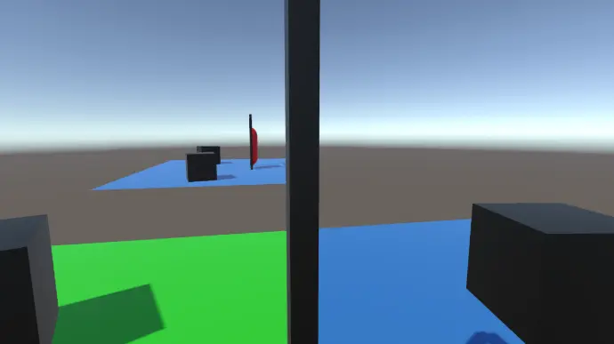
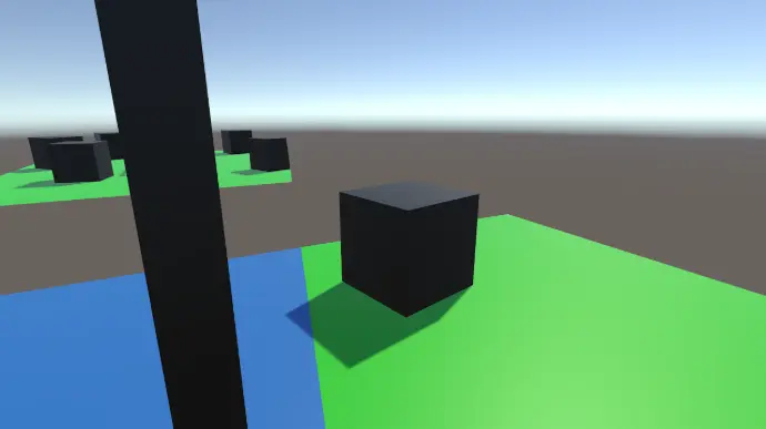
Deferred rendering & Volumetric lights
Deferred rendering is the last topic covered in this course. This uses a GBuffer to separate the ambient light, diffuse color, specular and normals into different targets, then combining all these during the main directional light pass. Finally, volumetric lights can be added afterwards.
The test scene consists of the famous Sponza scene, a flickering and moving green point light, and a static red spotlight in the back.
Implemented features
- Uber shader
- Geometry shader
- Sprite rendering
- Text rendering
- Hardware animations
- Camera picking
- Shadow mapping
- Particle systems and rendering
- Post-processing effects
- Deferred rendering
- Volumetric lighting
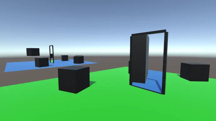
Portal Prototype
I am planning to recreate the well known game of Portal. It will be implemented using a custom C++ engine, using DirectX11 and the Effects Framework. This project serves as a test environment for me to learn how to make working portals in an existing game engine, Unity in this case.
The project is available on GitHub!
Video walkthrough
Future Work
This implementation does not support recursive portals at the moment. Recursive portal is the case where one portal is visible through the other portal, creating a potentially infinite recursion of portals. To manage this case, additional render target and render passes are required per recursion. This is a relatively expensive operation and has to be limited to a maximum recursion depth.
I will also look into another approach to render the portals, using the stencil buffer. This approach allows to render the scene in a single pass. Starting from the main camera, all opaques are rendered. Rendering the portal increases the stencil buffer. Once done, the opaque pass gets restarted with the correct camera transform, only writing to pixels where the stencil buffer is equal to 1. Once no portal is visible, or the maximum recursion has been reached, transparent objects can now be rendered, starting from the deepest portal back to the main camera. This video explains both approaches, as well as the encountered issues, and was used as a reference.
Oblique projection
One final issue with the portal's camera, being pushed away from the portal to give the correct perspective, is that other scene object can become visible on the portal's rendering. To prevent this, oblique projection is used to align the near clipping plane of the portal's camera to be aligned with the portal's screen, so every object that could block the view gets clipped away.
Add a clone and slice it
Another important part of the illusion is to have a visual representation of the traveler on the other side of the portal. The first time a traveler enters a portal trigger, a clone gets created and cached for future uses. The clone and the original traveler get sliced as well, so they do not remain visible on the other side of the portal's screen.
Fix artefacts
One issue that spoils the illusion is the near clipping plane of the player's camera clipping through the portal's screen, revealing what's behind the portal. To fix this issue, when the player enters the portal's trigger box, the portal's screen become thick enough on the back side so the camera cannot clip through it. This screen needs then to be double sided, so the texture is also visible once inside the screen. With the trigger fitting completely inside the portal's frame, it is not possible for the projected texture to be seen outside of the portal frame.
Teleporting the player
The portal has a trigger box covering the inside opening. Every object that can travel through the portal inherits from a base traveler class. This trigger box allows the portal to track those travelers that can potentially cross the portal, and knows if this happens by comparing on which side of the portal the traveler is versus previous frame. If the side is different, the traveler has then crossed the portal, gets moved to the output portal, according to both portal's transforms, and is now tracked by the output portal, until he leaves the trigger box.
Rendering the portals
I opted for the render texture approach, meaning each portal has a camera and a render target. Every frame, the camera's transform is updated according to the new main camera's transform. The cameras then get rendered onto the portal's render target before the main camera. The textures are assigned to the linked portal's screen material, to be displayed on the other portal. The UV's of the portal's screen are aligned based on their screen-space position, so the portal appears aligned and non-deformed.
Software/Hardware Rasterizer
This is my final assignment for my course Graphics Programming 1, where we learned how a ray-tracer and a rasterizer work, as well as an introduction to DirectX 11, using the Effects Framework. The project consists of two rasterizers, one software based, running on the CPU, as well as a hardware one, running on the GPU, and it is possible to switch seamlessly from one to the other.
The project is available on GitHub!
Topics covered
- Linear algebra (vectors and matrices)
- Left-handed and Right-handed coordinate systems
- Perspective projection
- Depth buffer
- Vertex interpolation
- Texture mapping, sampling and filtering
- PBR materials
- DirectX12 renderer
- PBR Materials
- Transparency (partial coverage)
- DirectX pipeline
- OBJ file parsing
Credits
Credits to Matthieu Delaere, former DAE lecturer, for the base framework implementation.
Recent rework
Replacement of raw pointers with unique pointers for all homemade classes, as well as COM pointers for DirectX objects.
Software Rasterizer